In this article, we will first write a GPIO driver to control LED using Python, and then connect it to Shifu for interaction and management.
Create the driver
Objective
- Complete simple LED circuit connection
- Basic Raspberry Pi/SSH configuration
- Basic Python syntax and knowledge of GPIO libraries
Devices
- Raspberry Pi
Raspberry Pi 3B+running 64-bitRaspberry Pi OS - 1 breadboard
- 3 LED bulbs (red, yellow, green)
- 1 x 330 ohm resistor
Basic knowledge
- Simple Python syntax
- Basic Linux command line operations (create files, install apps, SSH, run programs)
Step 1 Circuit design
First let's design the circuit. We need to design a circuit that will allow the GPIO output of the Raspberry Pi to control the on/off of a single LED bulb. In this article, we have used the most straightforward approach, i.e., using GPIO directly to power the LED bulbs.
The circuit diagram is as follows.
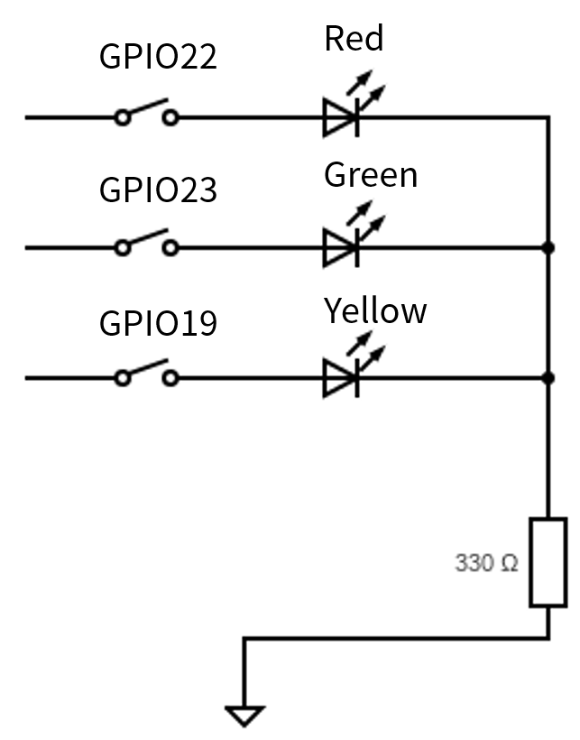
The GPIO pins 22, 23, and 19 control the red, green, and yellow LEDs respectively. 330 ohms resistors are connected in series at the end to prevent the LEDs from burning out due to excessive current.
Step 2 Circuit Implementation
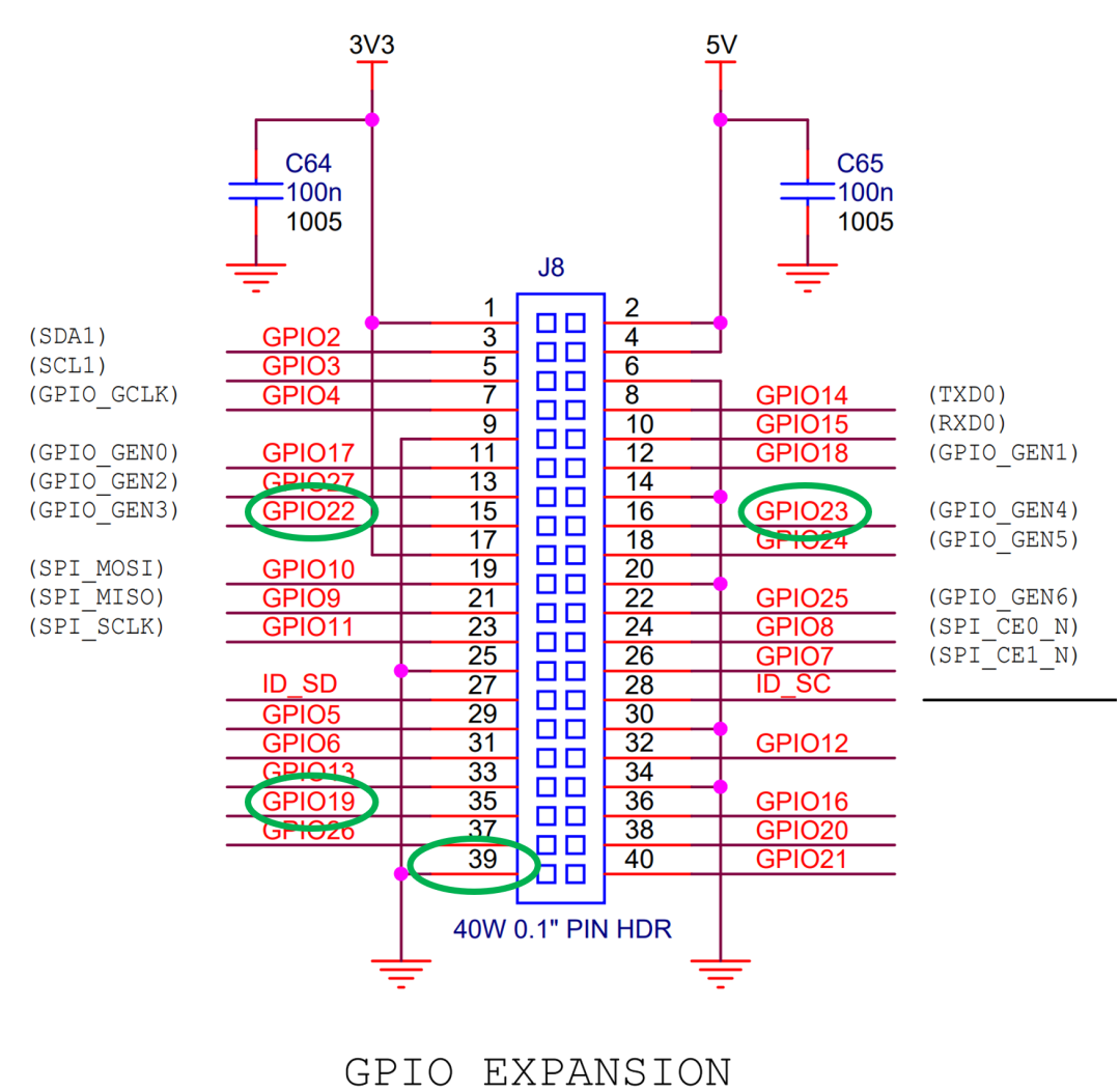
According to the Pin Layout in the official Raspberry Pi documentation, we can see the exact location of the pins, here pins 15, 16, 35 and 39 are used.
Connect these four pins to the female port of the cable, and then connect the remaining circuits on the breadboard too.
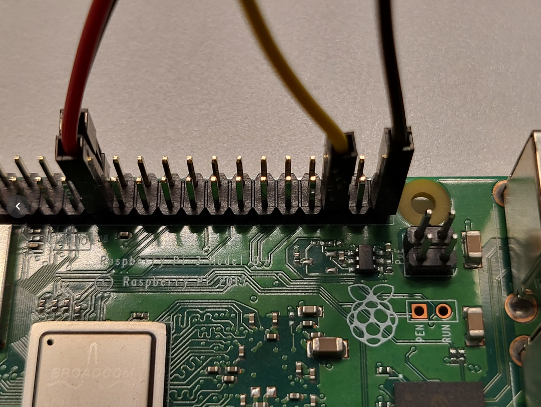
The red, green, yellow, and gray cables in the diagram correspond to GPIO22 GPIO23 GPIO19 and ground, respectively.
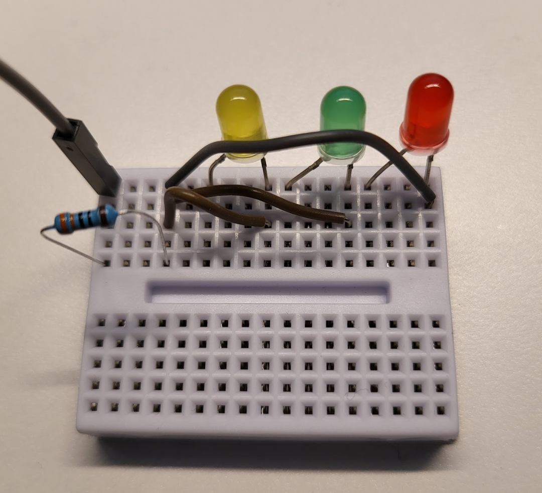
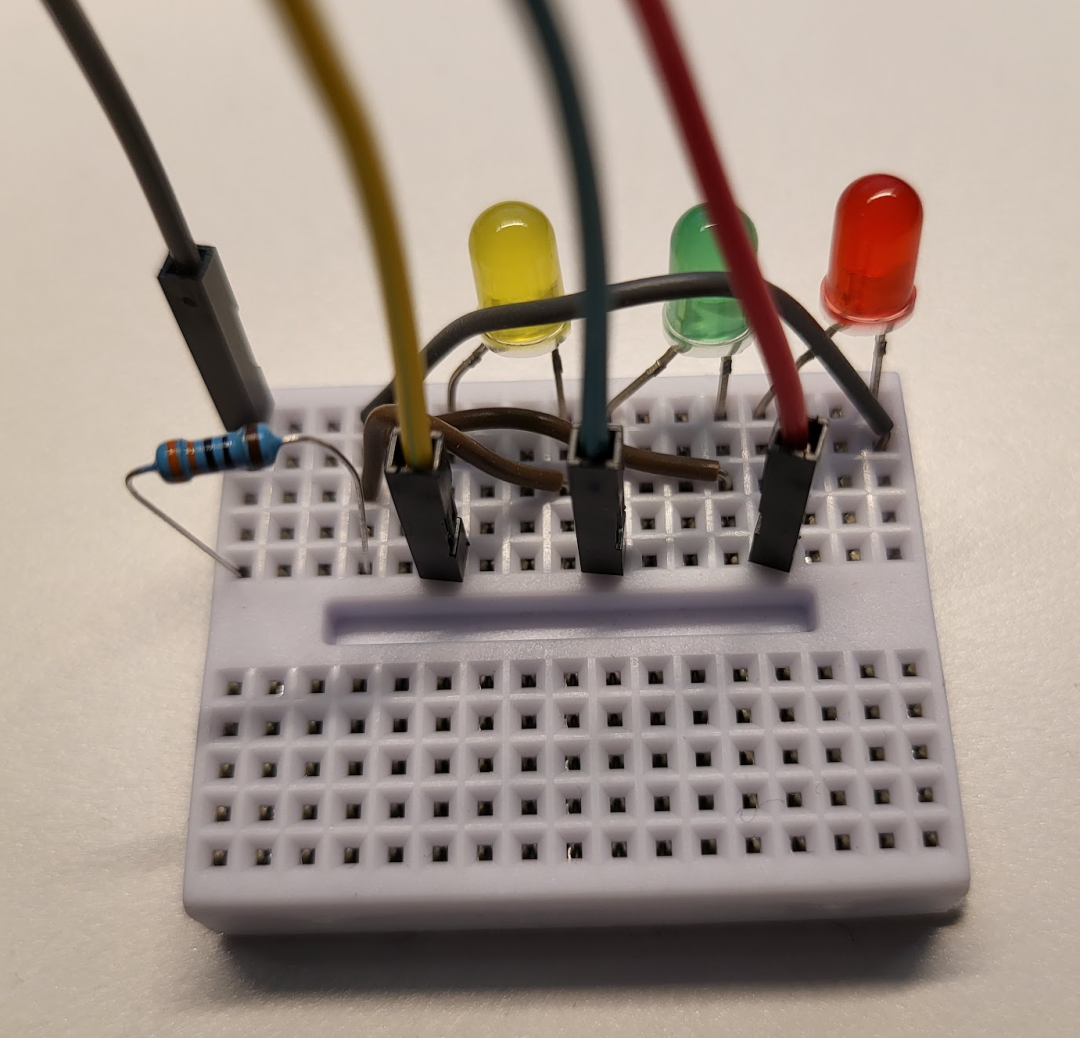
This concludes the circuit design and connectivity section.
Step 3 Raspberry Pi Preparation
First install an operating system in the Raspberry Pi, the one used in this article is Raspberry Pi OS (64-bit). download link
Insert the SD card into the reader, connect it to the USB port of your computer, and then swipe the downloaded zip file into the SD card via balenaEtcher. balenaEtcher link
Insert the SD card into the Raspberry Pi, plug in the power and monitor cable, and we can start the configuration.
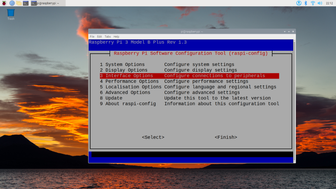
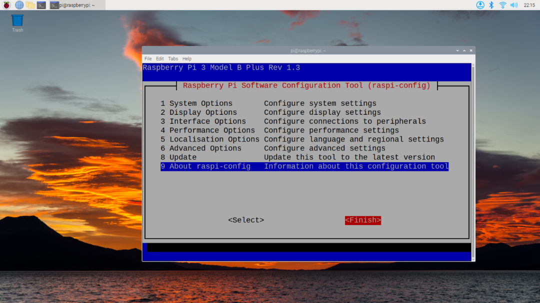
First, for development/debugging we need to enable SSH, open a terminal from the desktop and enter sudo raspi-config to access the configuration screen and select Interface Options.
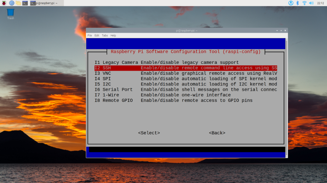
Select SSH:
Press enter, then press left to select Yes to enable the SSH service: <img src="/blog-220507/7.png
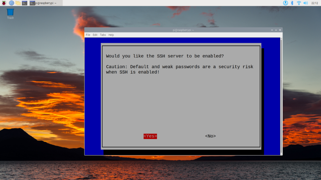
After that, press right and select Finish, then enter to exit.
At this point, the SSH service is on, but we need to know the IP of the Raspberry Pi in order to SSH, so we can check it with the built-in ip addr command.
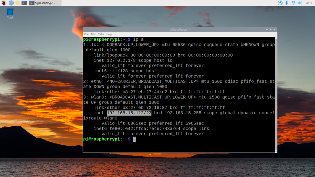
As you can see, the IP address is 192.168.15.122.
Back in the computer, you can remotely access the Raspberry Pi from the command line via ssh pi@192.168.15.122
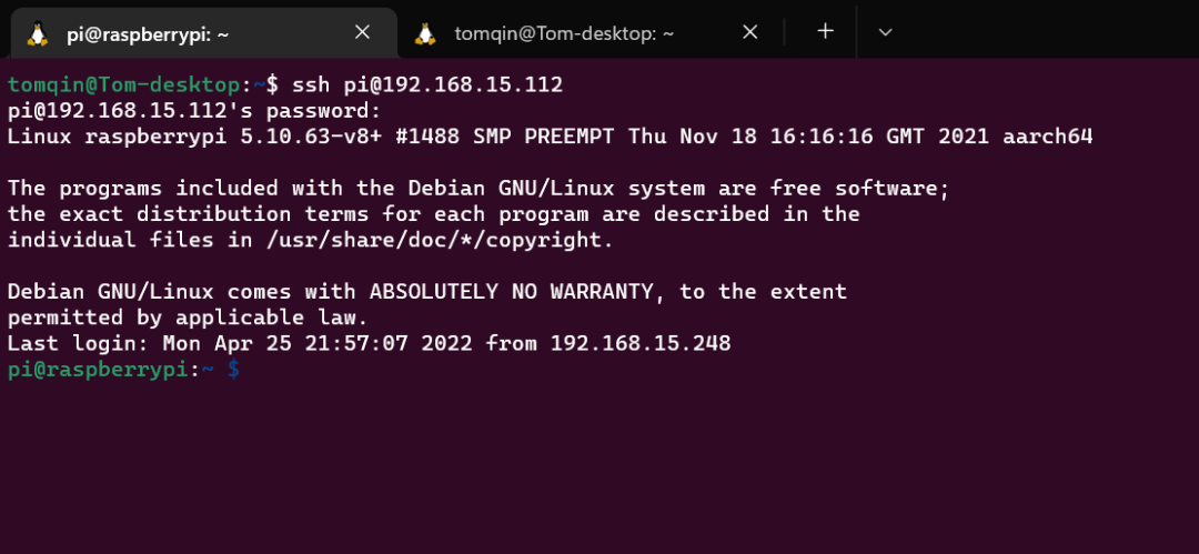
This concludes the preparation of the Raspberry Pi and the hardware.
Earlier versions of the Raspberry Pi OS may need to manually enable GPIO
Step 4 Write a Driver
Everything is in place, now let's write the first driver!
First make sure that Python is installed on your system, if not you can run the following command.
$ sudo apt-get update && sudo apt install python3 -y
After installation, you can check the status of the installation with python -V, if it shows the version, then the installation is successful:
$ python -V
Python 3.9.2
Next let's start with an LED bulb control, we want to control the red LED on/off using the following code.
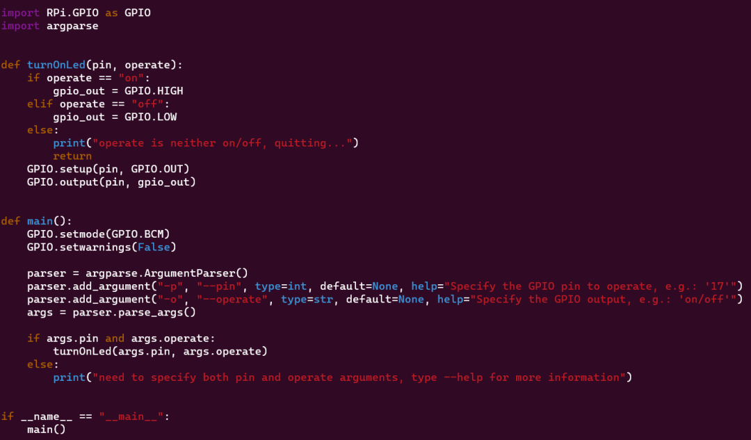
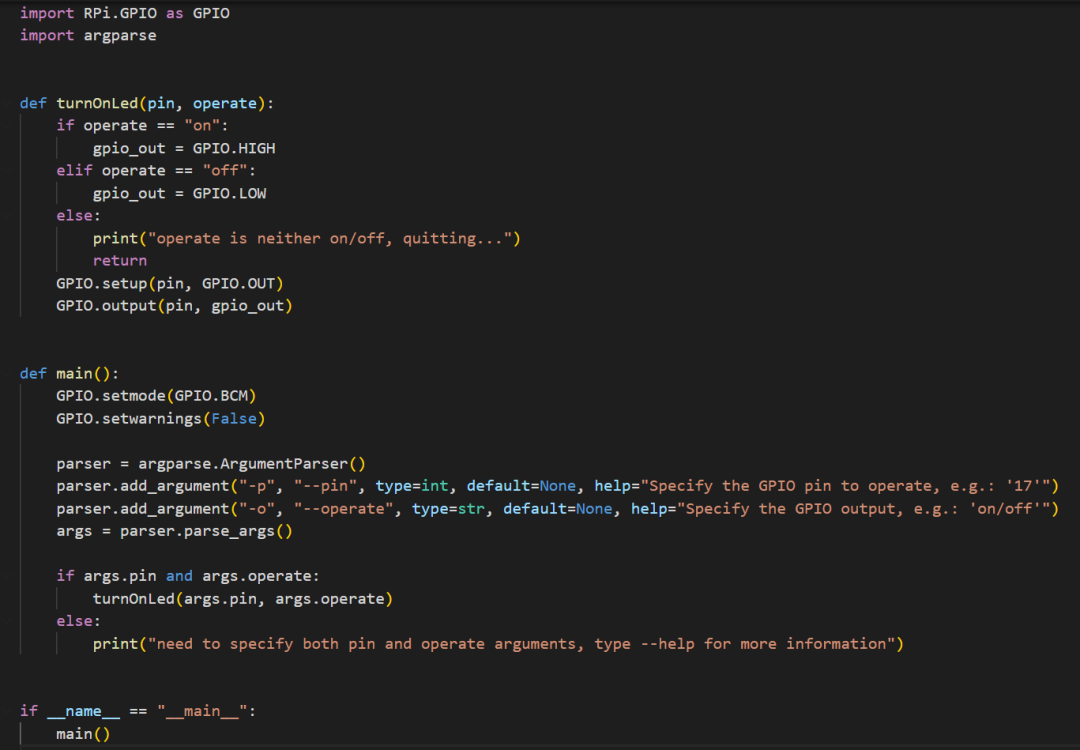
The modules used in the driver are:
RPi.GPIOto control the GPIO of the Raspberry Piargparseis used to parse command line input
First set the GPIO mode to GPIO.BCM mode, in this mode the pin numbers are the GPIO numbers, not the pin order on the Raspberry Pi board.
GPIO.setmode(GPIO.BCM)
Then turn the warning off, the Raspberry Pi will only be controlled only by this driver in this article.
GPIO.setwarnings(False)
Next process the program input, this driver will accept two inputs.
-p,--port, representing the GPIO pin that the program is manipulating-o,--operate, represents the program's operation of the GPIO pin,onrepresents1, i.e.3.3Vin the circuit,offrepresents0, i.e.0Vin the circuit
The code is as follows
parser = argparse.ArgumentParser()
parser.add_argument("-p", "--pin", type=int, default=None, help="Specify the GPIO pin to operate, e.g.: '17'")
parser.add_argument("-o", "--operate", type=str, default=None, help="Specify the GPIO output, e.g.: 'on/off'")
args = parser.parse_args()
Next we need to handle errors, passing the arguments into the function turnOnLed to operate when the pin count and operation are not empty, otherwise printing a warning
if args.pin and args.operate:
    turnOnLed(args.pin, args.operator)
else:
    print("need to specify both pin and operate arguments, type --help for more information")
The main part of the program ends, so let's look at the function turnOnLed that controls the LED bulb.
The first thing is to determine whether the operate variable is on or off, otherwise it returns. The output variable gpio_out is set to GPIO.HIGH when the variable is on and to GPIO.LOW when it is off.
These two values represent on or off.
if operate == "on":
    gpio_out = GPIO.HIGH
elif operate == "off":
    gpio_out = GPIO.LOW
else:
    print("operate is neither on/off, quitting...")
    return
The last thing is to set the mode of the pin to output: GPIO.setup(pin, GPIO.OUT)
and switch the pin's output to on/off: GPIO.output(pin, gpio_out)
Outcome
The program can be executed using python led_driver.py -p {pin #} -o {operate}
If we want to make the red bulb light up, we run python led_driver.py -p 22 -o on
And that's it, a simple control LED bulb driver for Raspberry Pi!
This driver essentially manipulates Raspberry Pi GPIO pin, so we can also use this driver to manipulate any circuit that can be controlled by 3.3V, and the pins are not limited to 22, 23 and 19 in this article. You can use your imagination to create a variety of test circuits.
Integrate into Shifu
Next, we use the driver we wrote to access the Shifu framework for interaction and management.
The Shifu architecture in this article is as follows.
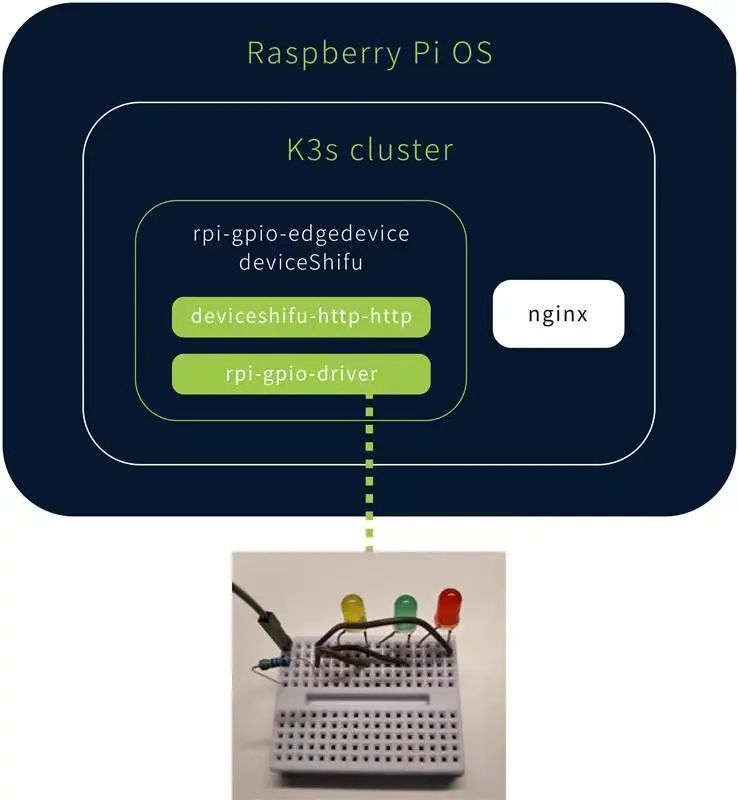
The northbound opens up the HTTP API interface via deviceshifu-http-http and the southbound interacts with the actual device via rpio-gpio-driver.
Objectives
- install k3s cluster on Raspberry Pi and install Shifu Framework
- package the Raspberry Pi LED driver to a container image
- deploy the digital twin of the Raspberry Pi LED in Shifu
- Achieve remote automation control of Raspberry Pi LEDs
Devices
- Raspberry Pi
Raspberry Pi 3B+running 64-bitRaspberry Pi OS
Basic knowledge
- basic operation of Docker/containerd
- basic operation of K8s/K3s
Step 1 Install k3s
First we need to run a Kubernetes cluster in the Raspberry Pi. There is no restriction on the version users can use here, but to save resources we use k3s in this article. Installation Tutorial
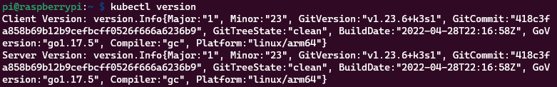
After installation, run kubectl version to see the current Kubernetes version.
Use kubectl get nodes to see the status of the current cluster, showing Ready means the cluster is available:
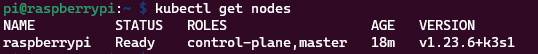
At this point, the k3s installation is complete.
Step 2 Install Shifu
First clone the Shifu project repository on your computer:
$ git clone https://github.com/Edgenesis/shifu.git
You can deploy Shifu to the k3s cluster with one click by using kubectl apply -f shifu/pkg/k8s/crd/install/shifu_install.yml.
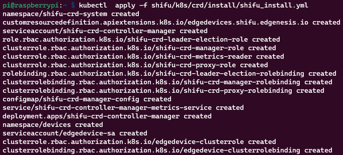
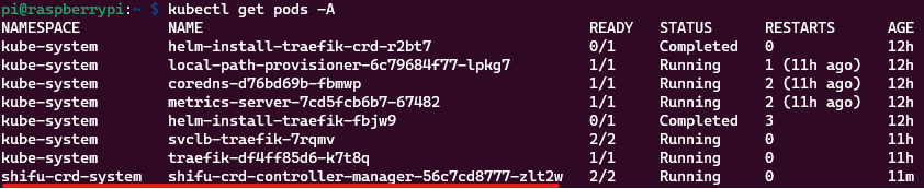
Execute kubectl get pods -A again to see the Shifu Framework controller deployed to the cluster: <img src="/blog-220507/connect-3.png
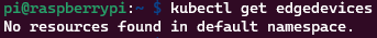
We can also manage device resources (currently there are no devices) via edgedevices the CRD: <img src="/blog-220507/connect-4.png
At this point, Shifu is successfully installed.
Step 3 Package the driver
We need to use a small tool provided by Shifu to realize that we can manipulate the local driver remotely, for a detailed tutorial please see.
- New version: https://github.com/Edgenesis/shifu/tree/main/cmd/httpstub/sshstub
- Older version: https://github.com/Edgenesis/shifu/tree/c0cab1ce98870eb470ddc9e01e1d99c13b611411/driver_util
This tool helps to convert HTTP requests sent by the user/program to a local command line for execution.
A sample driver is provided inside the tutorial at https://github.com/Edgenesis/shifu/blob/main/examples/driver_utils/simple-alpine/Dockerfile.sample
The content is as follows.
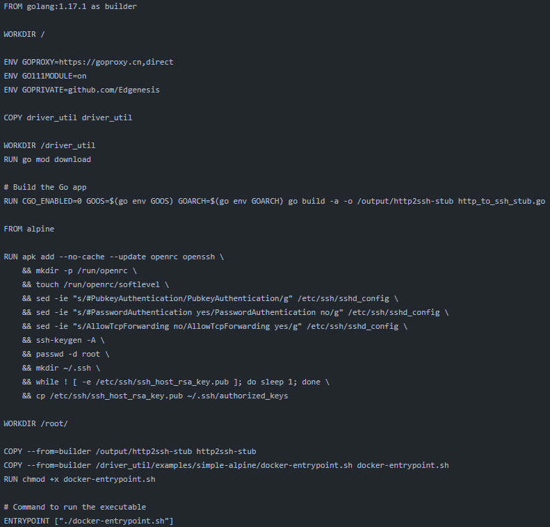
You can see that the Dockerfile has two parts, the first is to use the golang image to compile the http_to_ssh_stub.go provided by Shifu to convert HTTP command to SSH command. The next step is to use an empty alpine image to configure SSH for demonstration.
Next let's practice it.
Considering the limitations of Raspberry Pi, this compilation will be executed from the computer side, and the compiled image will be pushed to Docker Hub for remote invocation.
First, we create a new folder, here we use dev, and then save the created Raspberry Pi LED driver to this directory:.
dev/
└── led_driver.py
The driver content remains the same.
Copy Dockerfile.sample from the driver_util/examples/simple-alpine/ directory of the Shifu project to the dev directory.
dev/
├── Dockerfile.sample
└── led_driver.py
Change the following fields to change the second part of the image from alpine to python:alpine, install the Python library for RPi.GPIO
Finally, copy the Python driver into the run container, and the new Dockerfile will look like this, with the changes marked with comments.
FROM golang:1.17.1 as builder

WORKDIR /

ENV GOPROXY=https://goproxy.cn,direct
ENV GO111MODULE=on
ENV GOPRIVATE=github.com/Edgenesis

COPY driver_util driver_util

WORKDIR /driver_util
RUN go mod download

# Build the Go app
RUN CGO_ENABLED=0 GOOS=$(go env GOOS) GOARCH=$(go env GOARCH) gobuild -a -o /output/http2ssh-stub http_to_ssh_stub.go

FROM python:alpine # modified

RUN apk add --no-cache --update openrc openssh \
    && mkdir -p /run/openrc \
    && touch /run/openrc/softlevel \
    && sed -ie "s/#PubkeyAuthentication/PubkeyAuthentication/g"/etc/ssh/sshd_config \
    && sed -ie "s/#PasswordAuthenticationyes/PasswordAuthentication no/g" /etc/ssh/sshd_config \
    && sed -ie "s/AllowTcpForwardingno/AllowTcpForwarding yes/g" /etc/ssh/sshd_config \
    && echo"PubkeyAcceptedKeyTypes=+ssh-rsa" >>  /etc/ssh/ sshd_config\  # modified
    && ssh-keygen -A \
    && passwd -d root \
    && mkdir ~/.ssh \
    && while ! [ -e/etc/ssh/ssh_host_rsa_key.pub ]; do sleep 1; done \
    && cp /etc/ssh/ssh_host_rsa_key.pub~/.ssh/authorized_keys

RUN apk add --no-cache -Uu --virtual .build-dependencies libffi-devopenssl-dev build-base musl \
    && pip3 install --no-cache --upgrade RPi.GPIO\
    && apk del --purge .build-dependencies \
    && apk add --no-cache --purge curlca-certificates musl \
    && rm -rf /var/cache/apk/* /tmp/*  # modified

WORKDIR /root/

COPY --from=builder /output/http2ssh-stub http2ssh-stub
COPY --from=builder/driver_util/examples/simple-alpine/docker-entrypoint.sh docker-entrypoint.sh
COPY dev/led_driver.py led_driver.py  # modified
RUN chmod +x docker-entrypoint.sh

# Command to run the executable
ENTRYPOINT ["./docker-entrypoint.sh"]
Next we will package the Docker image, because the CPU of the Raspberry Pi is ARM64 processor, the computer used for compiling in this article is x86-64, so we need to use the buildx function of Docker to build the image, the tutorial about buildx will not be described in this article, you can move to https://docs.docker.com/buildx/working-with-buildx/.
Use docker buildx build --platform=linux/arm64 -f dev/Dockerfile.sample . -t edgehub/rpi-gpio-driver:v0.0.1 --push to build the image and push it to Docker Hub.
At this point, the image packaging part is complete.
Step 4 Deploy device twin to Raspberry Pi
Once we have the image, we can deploy the digital twin to the cluster, so let's prepare the files we need for the deployment.
First is a Kuberenetes Deployment YAML file to run deviceShifu and the driver Pod.
deviceshifu-rpi-gpio-deployment.yaml
apiVersion: apps/v1
kind: Deployment
metadata:
  labels:
    app: edgedevice-rpi-gpio-deployment
  name: edgedevice-rpi-gpio-deployment
  namespace: default
spec:
  replicas: 1
  selector:
    matchLabels:
      app: edgedevice-rpi-gpio-deployment
  template:
    metadata:
      labels:
        app: edgedevice-rpi-gpio-deployment
    spec:
      containers:
      - image: edgehub/deviceshifu-http-http:v0.0.1
        name: deviceshifu-http
        ports:
        - containerPort: 8080
        volumeMounts:
        - name: edgedevice-config
          mountPath: "/etc/edgedevice/config"
          readOnly: true
        env:
        - name: EDGEDEVICE_NAME
          value: "edgedevice-rpi-gpio"
        - name: EDGEDEVICE_NAMESPACE
          value: "devices"
      - image: edgehub/rpi-gpio-driver:v0.0.1
        name: driver
        volumeMounts:
        - mountPath: /dev/gpiomem
          name: gpiomem
        securityContext:
          privileged: true
        ports:
        - containerPort: 11112
        env:
        - name: EDGEDEVICE_DRIVER_SSH_KEY_PATH
          value: "/etc/ssh/ssh_host_rsa_key"
        - name: EDGEDEVICE_DRIVER_HTTP_PORT
          value: "11112"
        - name: EDGEDEVICE_DRIVER_EXEC_TIMEOUT_SECOND
          value: "5"
        - name: EDGEDEVICE_DRIVER_SSH_USER
          value: "root"
      volumes:
      - name: edgedevice-config
        configMap:
          name: rpi-gpio-configmap-0.0.1
      - name: gpiomem
        hostPath:
          path: /dev/gpiomem
      serviceAccountName: edgedevice-sa
Please note that in the Deployment file we need to add privileged: true to the container's securityContext, so that we can use the Raspberry Pi's GPIO in the container, then mount the Raspberry Pi's /dev/gpiomem to the container as volume.
Write a Kubernetes Service YAML file to proxy requests from the deviceShifu to the real Pod from the domain.
deviceshifu-rpi-gpio-service.yaml
apiVersion: v1
kind: Service
metadata:
  labels:
    app: edgedevice-rpi-gpio-deployment
  name: edgedevice-rpi-gpio
  namespace: default
spec:
  ports:
  - port: 80
    protocol: TCP
    targetPort: 8080
  selector:
    app: edgedevice-rpi-gpio-deployment
  type: LoadBalancer
A Kubernetes ConfigMap YAML file to configure deviceShifu.
deviceshifu-rpi-gpio-configmap.yaml
apiVersion: v1
kind: ConfigMap
metadata:
  name: rpi-gpio-configmap-0.0.1
  namespace: default
data:
  driverProperties: |
    driverSku: RaspberryPiB+
    driverImage: edgenesis/rpi-gpio-python:v0.0.1
    driverExecution: "python led_driver.py"
  instructions: |
    pin:
    operate:
    help:
# Telemetries are configurable health checks of the EdgeDevice
# Developer/user can configure certain instructions to be usedas health check # of the device.
# of the device. In this example, the device_health telemetry ismapped to
# "get_status" instruction, executed every 1000 ms
  telemetries: |
    device_health:
      properties:
        instruction: help
        initialDelayMs: 1000
        intervalMs: 1000
In ConfigMap we need to configure the execution path of the driver, because we put the Python file directly under the default path when generating the image, just fill in python led_driver.py here. If the driver is a binary file, you can directly fill in the binary directory here.
Write a Shifu EdgeDevice YAML file to generate the device twin.
edgedevice-rpi-gpio-edgedevice.yaml
apiVersion: shifu.edgenesis.io/v1alpha1
kind: EdgeDevice
metadata:
  name: edgedevice-rpi-gpio
  namespace: devices
spec:
  sku: "RaspberryPi 3B+"
  connection: Ethernet
  address: 0.0.0.0:11112
  protocol: HTTPCommandline
Put these four files into the Raspberry Pi with the following directory contents.
led-deploy/
├──deviceshifu-rpi-gpio-configmap.yaml
├──deviceshifu-rpi-gpio-deployment.yaml
├──deviceshifu-rpi-gpio-service.yaml
└──edgedevice-rpi-gpio-edgedevice.yaml
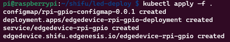
Use kubectl apply -f <dir> to deploy deviceShifu to the k3s cluster:
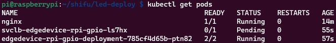
Then check the running status with kubectl get pods.
View all device twins in the cluster with kubectl get edgedevices -n devices.

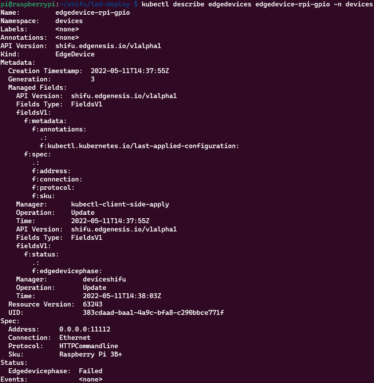
To see the details of the digital twin via describe.
Next we can interact with the device, where we deploy an nginx container to represent the application in a real-world scenario
The deployment command is kubectl run nginx --image=nginx
Then execute kubectl exec -it nginx -- bash to get to the nginx command line

Finally, using curl to send commands to the device, the driver accepts commands in the format: python led_driver --pin <x> --operate <on/off>
Using Shifu to send commands will convert from HTTP to command line, the request address is written as: http://edgedevice-rpi-gpio/pin?flags_no_parameter=<pin>,--operate,<on/off>
Outcome
The program can control the LED bulb on/off by sending an HTTP request directly to the device's domain name.
At this point, we have successfully plugged the Raspberry Pi driver into Shifu.